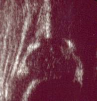
The Graf Technique relies on a quality image being generated in the standard plane so that reproducible measurements (α and β angles) can be used to quantify the bony and cartilaginous roofs, These values can be used to classify the severity of the hip dysplasia and comparisons made over time to evaluate the progression of the dysplastic joint.

A neonatal hip ultrasound, using the Graf technique.

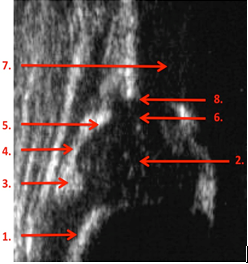
Hip ultrasound demonstrating the anatomical structures;
- Chondro-osseous border
- Femoral head
- Synovial fold
- Capsule
- Labrum
- Cartilage roof
- Bony roof
- Bony rim
1. Chondro-osseous border
This is the junction between the osseous metaphysis and the cartilaginous femoral neck.
2. Femoral head
The immature cartilaginous head (black) contains echoes (white), these are vascular lakes or sinusoids.
3. Synovial fold
This is the point of reflection of the capsule off the femoral neck.
4. Capsule
This continues upwards to insert into the perichondrium of the iliac bone.
5. Labrum
This is the bright triangular echo of fibrocartilage that lies beneath the capsule adjacent to the femoral head.
6. Cartilage roof
The hyaline cartilage roof is attached to the bony roof of the acetabulum. It appears black as if there is an echo gap.
7. Bony roof
The bony acetabular roof should cover more than 50% of the femoral head.
8. Bony rim
This is the most lateral part of the concavity of the bony socket, where it changes to the convexity of the iliac bone.

The standard plane ensures that the coronal image is taken through the absolute centre of the acetabulum without any tilting errors. This allows consistency between scans for comparison and accurate measurements.
1. Lower limb
This cuts through the central depth of the acetabular fossa.
2. Plane
A vertical line tangential to the iliac bone demonstrates the mid portion of the acetabulum.
3. The labrum

Measurement of the a and b angles.
The base line (Line 1) starts from the uppermost point of the proximal perichondrium and is drawn caudally tangential to the iliac bone. The bony roof line (Line 2) starts from the inferior border of the lower limb and is drawn tangential to the bony roof. The cartilage roof line (Line 3) is drawn between the bony rim and the centre of the labrum. The a angle is between lines 1. And 2. The b angle is measured between lines 1. And 3.

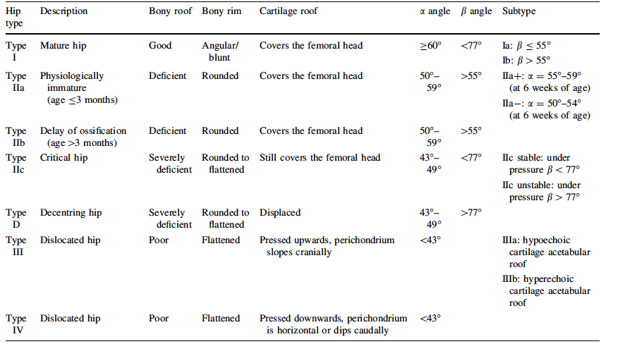
This demonstrates a Type I hip.
- This is a normal mature hip joint.
- The roof coverage is good.
- The bony rim may be angular or slightly blunted.
- The hyaline cartilage covers the femoral head.
- Alpha angle > 60 degrees
- The Beta angle is a research measurement to look at over/ under coverage of the hyaline cartilage roof.
A normal hip can deteriorate over time due to;
- Neuromuscular hip dislocation
- Wrong diagnosis and classification
- Effusion
- Secondary growth disturbance (from previously treated and normalized hips).
Type IIa
- This is considered an immature hip.
- The alpha angle is between 50 – 59 degrees. The child is below 12 weeks of age. (With premature babies it is advised to classify according to their calendar age but treat in accordance with their corrected gestational age).
Type IIb
- This is a mildly dysplastic joint
- The alpha angle is between 50 – 59 degrees. The child is greater than 12 weeks of age.
Type IIc
- This is a severely dysplastic hip.
- The alpha angle is between 43 – 50 degrees. It is close to being decentred (but not dislocated).
- The beta angle is less than 77 degrees.

Type II hip
Type D
- This is a severely dysplastic hip that can decentre (note D for decentred hip). The alpha angle is between 43 – 50 degrees (as with a IIc hip).
- The beta angle is greater than 77 degrees

Type III hip
- This is a dislocated hip.
- The labrum and hyaline cartilage roof are pressed upwards.
- The alpha angle is less than 43 degrees.

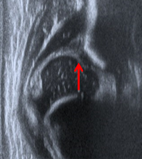
Type IV hip. The arrow demonstrates that the labrum and hyaline cartilage is pushed downwards
- This is a dislocated hip
- The labrum and hyaline cartilage is pressed downwards.
- The alpha angle is less than 43 degrees.

A comparison of all the sonographic hip types according to Graf.