TOPIC DETAILS

  Team Member Role(s) Profile
Paul Banaszkiewicz Paul Banaszkiewicz Section Editor
Richard Hutchinson Richard Hutchinson Segment Author
  • Being asked to draw a stress-strain curve or describe the properties of bone cement are popular viva topics in the FRCS (Orth) exam. The key to tackling these questions lies in having a good understanding of the basic principles of material science, in particular understanding engineering terminology.
  • We therefore begin this chapter explaining common material science terms with short and simple definitions. Then build on these “basics” to tackle the “ins and outs” of the stress-strain curve, viscoelasticity and finally the material properties of some commonly used orthopaedic materials.

NB. Definitions are highlighted in italics.

  • Material = a physical substance from which structures can be made.

The properties of a material depend on its internal architecture, e.g. the types of bonds between atoms (covalent, ionic, etc.), the arrangement of atoms (crystalline/amorphous), etc.

  • Structure = an object composed of material(s) in a given arrangement for a specific purpose(s) e.g. bearing load.
  • The properties of a structure depend on four things:
    • The material(s) its composed of
    • The volume of material used
    • The external shape of the structure
    • The internal arrangement of the material(s) within the structure
  • Therefore the material properties of an implant are independent of the implant’s size or shape.
  • The following is a list of terms (and their definitions) commonly used in bioengineering:
  • Deformation: Change in shape.
  • Elastic deformation: A change in shape under load, which is completely reversed once the load is removed – intermolecular bonds are stretched (to allow shape change) but not broken.1
  • Plastic deformation: A change in shape under load, which persists after the load is removed (i.e. permanent) – intermolecular bonds are broken and reformed elsewhere.1 Therefore in plastic deformation the object is given a new shape.
  • Elasticity: The ability of a material/structure to return to its original shape, following deformation through loading.
  • Tensile load: Collinear forces applied to a material/structure in order to pull it apart – causes lengthening of the object in the direction parallel to the force and shortening in the direction perpendicular to the force (see Figure 1a).
  • Compressive load: Collinear forces applied to a material/structure in order to push it together – causes shortening of the object in the direction parallel to the force and lengthening in the direction perpendicular to the force (see Figure 1b).
  • Direct force: Collinear forces applied along the axis of the material/structure – causes linear deformation. Tensile and compressive loads are both direct forces.
  • Shear force: Unaligned forces applied away from the material/structural axis – causes angular deformation (see Figure 1c).

BS7BIOMATERIALS1(a).png


BS7BIOMATERIALS1(b).png


BS7BIOMATERIALS1(c).png

Figure 1. These diagrams demonstrate the effects of (a) tension, (b) compression, and (c) shear on an object.

  • Stress: Force (F) applied to a material per unit area (A).

Units = N/m2
Normal stress (σ) – due to direct (tensile/compressive) forces.
Shear stress (τ) – due to shear forces.
Volumetric stress – normal and shear stress will always change the object’s shape. In volumetric stress equal compressive/tensile/shear forces are applied to an object causing its volume to change but its shape remains unaltered (e.g. a submarine’s volume will decrease in deep water due to hydrostatic compressive forces acting on all sides, but as all the forces acting on it are equal, the shape remains constant).2

t = F/A                 ∈ = ΔL/L

  • Strain: Quantative measure of material deformation. Direct strain (ε) = change in length (?L)/original length (L).

Direct strain has no units as it equates to a length (in m), divided by another length (also in m).
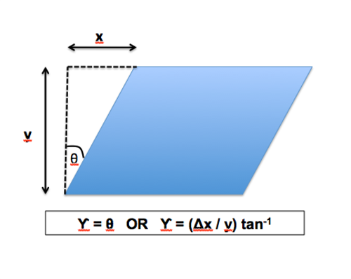
Shear strain (U) = angle of deformation (q). This can be difficult to measure directly as these angles are often very small. Therefore they can be calculated using the equation in Figure 2.
θ Angle is often measured in radians (Rad), not degrees. However, like direct strain, shear strain has no units as officially it represents the change in angle over original angle.
Volumetric strain – change in volume/original volume.2
BS7BIOMATERIALS2.png

Figure 2. Figure showing how shear strain can be calculated.

  • Elastic modulus (aka. Young’s modulus)

E = σ /

    • Young’s modulus = material stiffness.

Young’s modulus (E) = stress (σ)/strain ().
This is a material property.

  • Hooke’s law: The stress applied to a material is directly proportional to the resultant strain. Young’s modulus acts as the constant in the equation. Hooke’s law can therefore be written as:

σ = E
It is equal to the gradient of the stress/strain curve within the elastic zone (see Figure 3).1
Units = N/m2
NB. Some materials (e.g. polymers, biological tissue) demonstrate non-linear elasticity. This means the stress applied does not cause a proportional change in strain (i.e. it does not obey Hooke’s law); however, when the load is released the material returns to its original shape. These materials therefore do not have a measurable Young’s modulus. Instead a tangent modulus is taken from a chosen point on the stress-strain curve (see Figure 3b).1

BS7BIOMATERIALS3(a).png

Figure 3a. Stress-strain curve of material obeying Hooke’s Law, demonstrating how to calculate the Young’s modulus.

BS7BIOMATERIALS3(b).png
3b. Stress-strain curve of a material with non-linear elastic properties, demonstrating how to calculate the tangent modulus.
  • Stiffness: Ability of a material/structure to resist deformation.

The stiffness of a material = ability to resist strain = Young’s modulus.
Stiffness of a structure = gradient of a load-displacement curve.
Units = N/m2.

  • Strength: Ability of a material/structure to resist loading.

The strength of a material = ability to resist stress.

  • Yield strength (aka yield point)Stress at which a material permanantly deforms (usually referred to as the stress at which 0.2% plastic strain has occurred).
  • Ultimate tensile stressThe greatest stress a material can withstand prior to failure. This is the highest point of a stress-strain curve.

Units = N/m2.

  • Hardness: Resistance to point loading.

Point loading = load applied to a small localised area on a structure/material (e.g. the tip of a screw scratching the surface of a metal plate), as opposed to a load affecting the entire structure/material (e.g. from bending moments produced across a femoral plate when the patient bears weight).
In orthopaedics hardness usually refers to resistance to stratches or indentations on a materials surface.

  • Toughness: Amount of energy a material can absorb prior to fracture.

Toughness = area under stress–strain curve.
Units = Joules/m3

  • Ductility: The amount of plastic deformation permitted prior to fracture.

This includes the deformation seen in the plastic, strain hardening and necking regions (of a stress–strain curve) combined.

  • Brittleness: opposite of ductility.

A brittle material allows little/no plastic deformation.

  • Isotropic: The material/structural properties are dependant of the direction of loading.

E.g. Cortical bone = isotropic, as resists greater loads which are directed along the axes of the haversian systems.

  • Anisotropic: The material/structural properties are independent of the direction of loading.

E.g. Woven bone = anisotropic, as the randomly arranged trabeculae allow near equal resistance to loading regardless of direction.

  • Crystalline: Atoms arranged in a regular lattice formation.

E.g. Metals, some ceramics.

  • Amorphous: Literally “without form” – there is no regular/organised arrangement of atoms.

E.g. Polymethylmetacrylate (PMMA/bone cement).

Figure. 4 shows a stress-strain curve for a metal under tension. Initially the strain produced rises proportionally to the applied stress (ie. Hooke’s law is obeyed). Then after a given stress the stretched intermolecular bonds begin to break and reform, leading to plastic deformation, with loss of proportionality. As stress continues to increase the material undergoes strain hardening, necking and eventually failure.

BS7BIOMATERIALS4.png

Figure 4. Stress-strain curve demonstrating the principles of Hooke's law, the points of the proportional limit, elastic limit, yield point, ultimate tensile strength and failure.

The area of yielding can be subdivided into three definite points:

  • Proportional limit = point at which Hooke’s law is no longer obeyed.
  • Elastic limit = point at which the plastic deformation starts to occur.
  • Yield point = point at which 0.2% plastic strain has occurred.

Identifying the exact points at which proportionality is lost or plastic deformation occurs is difficult. Calculating when 0.2% residual strain is present after the load has been released is relatively simple. For this reason the yield point is most commonly used in everyday practice.

  • The stress-strain curve can be subdivided into regions that describe the changes occurring within the material (see Figure 5a).
  • Elastic region – Hooke’s law obeyed.
  • Plastic region – irreversible deformation occurs.
  • Strain hardening (aka. “work hardening” or “cold working”).
    • Metals are crystalline, made up of an organised regular lattice structure.
    • Plastic deformation disrupts this lattice structure, through the breaking and reforming of bonds, leading to so called “dislocations,” i.e. irregularities in the normally uniform internal structure.
    • A dislocation acts as a deterrent, preventing further dislocations forming in its vicinity. This means as more dislocations are formed, greater stresses are required to form new dislocations.
    • Hence the plastic deformation actually makes the material more resistant to the stress applied (i.e. makes it stronger).
  • Necking:
    • Caused by a mismatch between the calculated and actual stress applied.
    • With each dislocation the material changes shape, but becomes stronger.
    • However, a point is reached when the benefit of these dislocations appears to diminish, and a decreasing amount of stress is required to continue to produce strain. This region is known as necking.
    • The downward slope of stress in the necking region is really a misinterpretation of what is actually occurring in the material.
  • As the material under tension is increasing in length, its cross-sectional area is gradually diminishing. The stress calculated in the curve is based on the tensile force being applied divided by the material’s original cross-sectional area. As the actual cross-sectional area decreases less force is required to produce the ever-increasing stress. If the stress in the graph was calculated from the actual cross-sectional area the curve would be seen to continue to rise until failure (see Figure 5b).

BS7BIOMATERIALS5(a).png


BS7BIOMATERIALS5(b).png

Figure 5(a) and (b). These stress-strain curves show (a) how stress effects strain in the different stages of elastic and plastic regions, and (b) how the actual and calculated curves in the necking region differ.

  • Figure 6 shows the stress–strain curve for three materials:
    • Material A – is the stiffest material (steepest gradient), but is very brittle, allowing no plastic deformation prior to failure. It also has the lowest ultimate tensile strength.
    • Material B – is the strongest material, with a greatest yield and ultimate tensile strength.
    • Material C – is the least stiff, but is very ductile, and overall is the toughest material.

BS7BIOMATERIALS6.png

Figure 6. This graph shows how stress-strain curves differ in different materials.

  • Viscoelasticity: A broad term incorporating any deformation that is both load and time dependent.
    • Literally means the material demonstrates viscous and elastic behaviour.
    • Creep, stress-relaxation, hysteresis and strain-rate-dependant behaviour are all types of viscoelastic behaviour.3
    • Most biological materials are viscoelastic (including bone).
  • Creep: Under a constant stress, strain increases with time.
    • E.g. The Ponseti technique for correcting CTEV relies on creep. The cast provides a constant load on the foot, but the tendons and ligaments lengthen over time (via creep).
  • Stress-relaxation: Under a constant strain, stress decreases with time.
    • E.g. Inserting a femoral broach into the canal relies on stress-relaxation. The broach is tapped in to a level where it puts a deforming strain (with an associated stress) on the canal (expanding it slightly). If the broach is tapped in too quickly the stress levels may rise high enough to cause fracture, but if there is some delay before passing the broach further (i.e. strain remains constant for some time), stress levels have a chance to drop, reducing fracture risk.
  • Hysteresis: The amount of energy stored during loading is greater than the amount released on unloading.4
    • When a material is loaded, energy is stored. On unloading energy is released.
    • In purely elastic materials the amount of energy stored on loading is equal to the amount released on unloading.
    • In viscoelastic materials the amount of energy released on unloading is less than that stored on loading. This energy is used up in the breaking and formation of intermolecular bonds, or lost as heat. This process of the material using up some of the energy given to it is called hysteresis (see Figure 7).
    • Viscoelastic materials result in a stress–strain curve where the loading and unloading curves differ in shape. The area formed between these curves equals the energy lost due to hysteresis.

BS7BIOMATERIALS7.png

Figure 7. Graph demonstrating how energy is lost from a material during hysteresis

  • Strain-rate-dependent behaviour: Strain produced is dependent on the rate at which the stress is applied.
    • These materials are non-Newtonian, i.e. the materials ability to resist stress is dependent on the speed at which the strain occurs.
    • Usually the greater the rate at which strain is induced (i.e. greater strain-rate), the more stress required.
    • E.g. When stretching out contracted joints in cerebral palsy, a slow and gradual increase in force allows the joint to move, whereas short sharp forces cause the resistance to joint movement to be much greater.

Polyethylene

  • The first Charnley THAs utilised polytetrafluoroethylene (better known as Teflon) as their soft bearing material. However, this led to an unacceptable early failure rate due to excessive wear. In 1962, Charnley tried using ultra-high molecular weight polyethylene (UHMWPE) instead, with great success.5 Since then UHMWPE has become a staple component in all hard-on-soft arthroplasty designs.

Molecular structure

  • Polymer made up of a very long chain of ~70,000–200,000 ethylene (C2H4) groups (see Figure 8).6
  • UHMWPE molecular weight = 3–6 million.7
  • Semi-crystalline structure – containing crystalline and amorphous phases (see Figure 9).5 Increasing the percentage of the crystalline phase decreases the risk of fatigue crack propagation.6
    • The amorphous phase is made up of a disorganised array of tangled polymer chains.
    • In the crystalline phase the chains have folded into more organised lamellae.

BS7BIOMATERIALS8(a).png


BS7BIOMATERIALS8(b).png

Figure 8. Diagrams showing the molecular structures of (a) ethylene and (b) polyethylene.

BS7BIOMATERIALS9.png

Figure 9. Schematic representation of the amorphous and crystalline polymer chains in UHMWPE.

Material properties

  • High impact strength (i.e. absorbs energy of sudden impact loads well).
  • Low coefficient of friction.
  • Viscoelastic
  • Non-toxic
  • Much better resistance to abrasion than Teflon.
  • Thermoplastic (i.e. material properties can be altered through temperature and radiation).8

Highly cross-linked polyethylene (HXLPE)

  • Normally, UHMWPE chains are held together by weak intermolecular Van Der Vaal’s forces.
  • Cross-linking = process of forming strong intermolecular covalent bonds between UHMWPE chains, increasing the force needed to pull the chains apart.7
  • Gamma-irradiation of UHMWPE causes cross-linking.
  • However, gamma-irradiation also causes free radical formation within UHMWPE. Free radicals then combine with O2 in oxidation reactions, leading to chain fragmentation. Ultimately this makes the material more brittle and reduces yield strength.7
  • To prevent this manufacturers have tried to stabilize UHMWPE (i.e. reduce free radical formation/oxidation) using different techniques:

Thermal stabilisation

  • Melting – after irradiation, UHMWPE is heating beyond its melting point (about 130°) and then cooled. This eliminates most of the free radicals, but as UHMWPE is thermoplastic, the heating process alters its microstructure, which may affect its mechanical properties.7
  • Annealing – after irradiation, UHMWPE is heated to a point below melting. This has a lesser effect on microstructure, but eliminates fewer free radicals.9

Vitamin E

  • Vitamin E = anti-oxidant. It is introduced into the UHMWPE to reduce the amount of oxidative reactions, without the need for heat treatment.9

Reduce O2 exposure

  • Sterilising/irradiating the polymer in nitrogen (as opposed to air) limits the amount the UHMWPE is exposed to O2, reducing the number of oxidative reactions. However the polymer will be exposed to O2 when removed from its packaging and through its dissolved form in bodily fluids.7
  • NB. When considering the rate of osteolytic loosening we cannot just focus on the number of wear particles produced. Particle size is also critical to the rate of implant failure. UHMWPE particles between 0.1 and 1 µm cause the greatest inflammatory response.8
  • Most metals are crystalline.
  • Metals consist of positive metal cations sitting in a “sea of shared electrons” (see Figure 10a). The electrons are given up from the outer electron shells of metal atoms, forming positive cations and free electrons. The electrical forces between the positive ions and free electrons are called metallic bonds. As no one electron is “assigned” to any particular cation, it is relatively easy for the cations to move position and form new metallic bonds elsewhere, without the overall structure being compromised (see Figure 10b). For this reason metals are relatively ductile.
  • Pure metals are too weak/reactive to have practical use in orthopaedics.3 Alloys are composites of different metals. Alloys allow us to utilise and combine the properties of pure metals, which on their own would be insufficient. There are three main alloys used in orthopaedics:8
    • Stainless steel (316L)
    • Cobalt–chromion
    • Titanium (Ti-6Al-4V or Ti-6Al-7Nb)

BS7BIOMATERIALS10(a).png


BS7BIOMATERIALS10(b).png

Figure 10 (a). showing the internal structure of metals (cations in a ‘sea of electrons’) and 10 (b). how this structure can allow plastic deformation.

Titanium alloys (Ti)

  • Composition:
    • There are two main Ti alloys used in orthopaedics. Traditionally, Ti-6Al-4V (titanium – 6% aluminium – 4% vanadium) was widely used; however, due to concerns that vanadium has cytotoxic effects, Ti-6Al-7Nb (titanium – 6% aluminium – 7% niobium) is now being used as an alternative.10
    • As well as titanium, aluminium and vanadium/niobium, they also contain small traces of: iron, tantalum, oxygen, carbon, hydrogen and nitrogen.10
  • Advantages:
    • High yield strength.
    • Undergoes “self-passivation” (i.e. forms protective oxide coating in situ) reducing corrosion.8
    • Young’s modulus closer to bone (see Table 1).
  • Pitfalls:
    • Poor wear resistance – not good as a bearing surface.8

Stainless steel (SS)

  • Composition:11
    • Implant quality type 316L SS was first introduced as an orthopaedic material in the 1950s.
    • Its main constituents are:
      • Iron (Fe) 65%
      • Chromion (Cr) 18%
      • Nickel (Ni) 14%
      • Molybdenum (Mo) 2.5%
    • It also contains traces of: carbon, copper, manganese, nitrogen, phosphorous, silicone and sulphur.
    • Ni, Cr and Mo help improve corrosion resistance.
    • The “L” stands for low carbon content (which also improves corrosion resistance).
  • Advantages:
    • Stiffer than Ti (SS has nearly twice the Young’s modulus of Ti) meaning it deforms less under the same strain (when it is behaving elastically).
    • Relatively cheap.
  • Pitfalls:
    • Due to the large discrepancy between the Young’s moduli of SS and bone (see Table 1) load bearing SS prostheses can cause stress shielding in surrounding bone increasing the risk of peri-prosthetic fracture. This has been partly dealt with by using a cement “buffer” (polymethylmethacrylate Young’s modulus = 3.1 GPa12).
    • More corrosive than Ti and Cr.
    • Potential risk of reaction in nickel allergy.

Cobalt-chromion (Co-Cr)

  • Composition:
    • Three main constituents:
      • Cobalt (Co) 63%
      • Chromium (Cr) 28%
      • Molybdenum (Mo) 6%
    • Also contains traces of: aluminium, boron, carbon, iron, manganese, nickel, nitrogen, phosphorous, silicone, sulphur, titanium, tungsten.
    • As with SS, molybdenum improves corrosion resistance.8
  • Advantages:
    • Better corrosion resistance and greater stiffness than SS.
    • Much better wear resistance compared with SS and Ti, hence it is commonly used as the metal of choice in metal bearing surfaces.
  • Pitfalls:
    • Stress-shielding, as with SS.

Table 1. Material properties of SS, Co-Cr, Ti and Bone (NB: The range is ultimate and yield strength seen in SS depends greatly on the manufacturing process used)


Young’s modulus (GPa)

Yield strength (MPa)

Ultimate tensile strength (MPa)

SS (316L)11

200

190–690

490–1400

Co-Cr13

240

560

960

Ti10

110

800

900

Cortical bone14

20

130

160

  • The ceramics commonly used in orthopaedics are compounds made up of metallic (e.g. aluminium) and non-metallic (e.g. oxygen) elements.3 The atoms within these compounds are joined by ionic/covalent bonds, which are both much stiffer and stronger than metallic bonds, found in pure metals and alloys.3
  • Ceramics used in orthopaedics are crystalline, consisting of a strict lattice structure. Breaking and reforming this structure into a different shape (i.e. plastically deforming) is not possible, due to the difficulty in rearranging the atoms back into a similar lattice formation.3 Therefore, ceramics are very brittle, with little to no plastic deformation prior to failure.
  • The two most common ceramics used as bearing materials are alumnia (Al3O2) and zirconia (ZrO2).7 Both laboratory and clinical studies have shown ceramic bearing surfaces produce less wear than metal bearing surfaces.15,16 However, the risk of catastrophic failure through liner/head fracture is a concern in ceramics.
  • Advantages:
    • Lower surface roughness than metals – resulting in a lower coefficient of friction and thus less wear.15
    • Very hard – i.e. resist surface scratch formation much better than metals. Scratches increases surface roughness, increasing wear.
    • Greater wettability than metals (see Figure 11):17
      • Wettability is a measure of how spread out a fluid droplet will be when it contacts a surface.
      • When fluid comes into contact with a surface, the shape that droplet of fluid takes on is dependent on the balance between the cohesive forces (pulling the liquid molecules together), and the adhesive forces (between the fluid and the surface).
      • With a hydrophilic surface, liquid molecules are more inclined to bond with surface molecules (as opposed to each other), meaning the fluid spreads out more across the surface – i.e. the surface is more wettable.
      • The advantage of a larger spread of fluid across the surface is that the fluid acts as a lubricant barrier, lowering the coefficient of friction, thus decreasing wear.
      • Ceramics are more hydrophilic than metals.
  • Bioinert – ceramics are more chemically stable than metals in the biological environment, meaning they are much better at resisting corrosion.6
  • High compressive strength.8

BS7BIOMATERIALS11(c).png

Figure 11. These figures demonstrate the principle of wettability. A greater θ angle (a) created between the fluid and surface occurs in less wettable materials. Figure (b) shows how the fluid behaves on a less wettable metal surface, compared with ceramic material in figure (c), which is more wettable. The black arrows represent the forces pulling water molecules to each other, where as the red arrows represent the hydrophilic pull from the material.

  • Pitfalls:
    • Very brittle – once a crack forms it will immediately propagate through the implant leading to fracture and catastrophic implant failure.
      • In THR, ceramic-on-ceramic bearings are often called “less forgiving,” as there is a smaller margin of error allowed when aligning the components. Aligning them outside this “safe zone” can lead to edge loading, which can lead to crack formation and failure.
    • Less strong in tension and shear.8
  • Bone cement (PMMA) was first introduced by Charnley, who was inspired by its use in dentistry.5
  • PMMA is mostly made up of two components:18
    • ‘P’owder polymer – contains polymethyl metahcrylate plus an initiator (di-benzoyl peroxide).
    • Liquid monomer – contains methyl methacrylate plus an accelerator/catalyst (N,N-dimethyl-p-toluidine).
  • These are mixed at room temperature, resulting in an exothermic polymerisation reaction.
  • PMMA is an amorphous material.

Additives

  • Certain substances are added to PMMA to improve its properties:18
    • Zirconium dioxide – added to polymer – allows it to be radio-opaque.
    • Colouring – added to polymer – (e.g. chlorophyll) allows easier visualisation of cement in the operative field.
    • Antibiotics – added to polymer – can be very useful in delivering high doses of antibiotics locally, to the surgical field.
    • Hydroquinone – added to monomer – stabilises the monomer. With exposure to light or temperature changes the monomer can undergo premature polymerisation in its container. Hydroquinone prevents this.

Properties

  • Acts as a GROUT. It is NOT adhesive.
    • As it is inserted into bone when it is less viscous, it can interlock with bony architecture to provide a secure cement–bone interface. However, with smooth highly polished implants, the cement allows movement at the implant–cement interface. This gives rise to the taper-slip mechanism used by many THR femoral stems.
  • Acts as a BUFFER between a stiff implant and less stiff bone (see Metals section), due to its low Young’s modulus (E = 3.1 GPa), reducing the effect of stress shielding.
  • Acts as a “DRUG DELIVERY SYSTEM,” allowing high doses of antibiotics to be delivered to the local area.
    • Studies have shown the mechanical properties of PMMA can be compromised with increasing doses of antibiotics. Therefore, if used, the overall benefit of antibiotics versus cement mantle failure should be considered when planning dosage.19
    • The antibiotics must be able to cope with the local exothermic reaction to be effective.
    • Antibiotics commonly used include:18,19
      • Gentamicin
      • Vancomycin
      • Cefuroxime
      • Tobramycin
  • Mechanical properties:8
    • Viscoelastic
    • Strongest in compression.
    • Weak in tension.
    • Weakest in shear.

CASE BASED DISCUSSIONS

Case based Discussuion :UHMWPE

Examiner:Tell me what do you understand by ultra high molecular weight polyethylene(UHMWPE)
Candidate:

  • This is a long chain polyethylene or polymer of ethylene (plastic).
  • Introduced modern arthroplasty era in early 60s, by pioneering work of Charnley.
  • Bearing couple of choice for most hip replacements is metal-on-polythylene.
  • Formed by addition polymerization.
  • Polyethylene is a thermoplastic polymer
  • Consists of long chains of the monomer ethylene (C2H4)
  • Formed by addition polymerization.
  • Free radicles break double carbon bond of ethylene, which then reforms in long carbon-carbon chains

Examiner: Why does the theatre sister ensure poly liners are stored in date order on the shelf in theatres? What happens if there’s a leak in the packing of an acetabular (socket) liner? 

Candidate: 

  • Oxidative degradation occurs. 
    • Residue free radicals contained in the PE reacts with leaked oxygen 
  • This reduces the lifespan of the polyethene after implantation. 
  • To address concerns for wear resistance: cross-linking by gamma irradiation in the absence of oxygen is used by manufacturers.  

EXAMINER: What about HCLPE 

Candidate: 

  • With HCLPE,  the polyethene is either remelting or annealing to reduce the concentration of free radicals  
  • Melting eliminates all free radicals but alters the mechanical properties of the PE 
  • Annealing leaves some free radicals behind which can react with oxygen and result in increased wear rates. However the mechanical properties are less affected  
  • Medium-term results highly cross-linked are favourable. 
  • First-generation highly cross-linked poly has better wear resistance, but mechanical properties are altered including fatigue strength and toughness. 
  • Second generation highly cross-linked poly involves sequential annealing  

Examiner:What do we mean by cystaline and amorphous phases of PE 

Candidate: 
Crystalline phase provides the mechanical properties to PE 
Amorphous phase-only the amorphous area can cross-link 

Previous
Next

QUESTION 1 OF 7

X During the manufacturing process of cross-linked UHMWPE Vitamin E is added to the polymer.
What is the primary role of Vitamin E in cross-linked UHMWPE.

QUESTION ID: 1142

1. Acts as a bactericidal agent
2. Increases cross-linking
3. Reduces risk of delamination
4. Reduces surface roughness
5. Works as an antioxidant agent

QUESTION 2 OF 7

Which of the following statements best describes the ‘yield point’ of a material:

QUESTION ID: 1144

1. A. The point at which elastic deformation starts to occur
2. B. The point at which necking starts to occur
3. C. The point at which plastic deformation starts to occur
4. D. The point at which work hardening starts to occur
5. E. The point of failure

QUESTION 3 OF 7

A metal is being tested for its material properties in a laboratory by undergoing cyclical loading, with increasing loads on each cycle. Its noted once loads are applied that exceed the materials yield point, the stress required to cause further plastic deformity goes up with each loading cycle.
Which of the following best describes the cause for this phenomenon:

QUESTION ID: 1149

1. A. Hooke’s law
2. B. Increasing grain size
3. C. Necking
4. D. Stress-shielding
5. E. Work-hardening

QUESTION 4 OF 7

Figure 1 shows a S-N curve for a stainless steel plate.
If X represents one load cycle what does point A on the y-axis demonstrate?

Figure 1 RH 2.png

QUESTION ID: 1198

1. Failure
2. The elastic limit
3. The endurance limit
4. The fatigue limit
5. The ultimate tensile strength

QUESTION 5 OF 7

During a total hip arthroplasty whilst waiting for cement to set after inserting a PE cup, there is a discussion about the HCLPE. The registrar is revising for her exams and asks the lead surgeon about the irradiation of HCLPE

QUESTION ID: 2169

1. Although crystalline areas cross link free radicals are still left behind leading to an oxidation risk
2. Amorphous phase provides mechanical properties to HCLPE
3. Cross linking of free radicals occurs during melting which prevents recrystallization
4. Only the crystalline area can cross link
5. Post irradiation annealing eliminates all free radicals but reduces the mechanical properties of HCLPE

QUESTION 6 OF 7

43. During the design process for an osteosynthesis device a novel material is considered.
A material that undergoes elastic deformation, but no plastic deformation is termed:

QUESTION ID: 2231

1. Anisotropic
2. Brittle
3. Ductile
4. Stiff
5. Viscoelastic

QUESTION 7 OF 7

64.Which of the following statements best describes passivation of implants?

QUESTION ID: 3261

1. A layer of oxide formed on a metal surface that prevents further reaction between the metal and enviroment.
2. Is an effective way to deal with fretting corrosion?
3. The addition of a reactive substance to the surface of the implant that with preferentially corrode rather than the implant.
4. The application of a surface finish to improve fracture mechanics.
5. The heating and cooling of an implant to reduce the internal strain.

Further Reading

  • 1. SS Malik, SS Malik. Orthopaedic Biomechanics: Made Easy (pp. 16–43) This covers a lot of material science basics.
  • 2. Miller MD. Review of Orthopaedics (pp. 120–124) Useful reference guide

References

  • 1. Calister WD, DG. Rethwisch DG. Materials science and engineering. 9th edn. Wiley, Asia, 2015.
  • 2. Hearn EJ. Mechanics of materials: An introduction to the mechanics of elastic and plastic deformation of solids and structural materials. 3rd edn. Butterworth-Heinemann, Oxford, UK,1997.
  • 3. Malik SS, Malik SS. Orthopaedic biomechanics made easy. 1st edn. Cambridge University Press, Cornwall, UK, 2015.
  • 4. TeachEngineering. https://www.teachengineering.org/view_lesson.php?url=collection/cub_/lessons/cub_surg/cub_surg_lesson04.xml 2017.
  • 5. Callaghan JJ, Rosenberg AG, Rubash HE. The adult hip. 2nd edn. Lippincott Williams & Wilkins, 2007.
  • 6. Santavirta S, Konttinen YT, Lappalainen R, et al. Materials in total joint replacement. Curr Orthopaed 1998; 12: 51–57.
  • 7. Heisel C, Silva M, Schmalzried TP. Bearing surface options for total hip replacement in young patients. JBJS (Am) 2003; 85-A(7): 1365–1379.
  • 8. Miller MD, Thompson SR, Hart JA. Review of orthopaedics. 6th edn. Elsevier Saunders, Philadelphia, USA, 2012.
  • 9. Garcia-Rey E, Garcia-Cimbrelo E. Polyethylene in total hip arthroplasty: half a century in the limelight. J Orthpaed Traumatol 2010; 11: 67–72.
  • 10. Disegi J. Implant Materials: Titanium – 6% aluminum – 7% niobium. 2nd edn. Synthese, Lausanne, Switzerland, 2008.
  • 11. Disegi J. Implant Materials: Wrought 18% Chromium – 14% Nickel – 2.5% Molybdenum. 3rd edn. Synthese, Lausanne, Switzerland, 2009.
  • 12. Matbase. http://www.matbase.com/material-categories/natural-and-synthetic-polymers/commodity-polymers/material-properties-of-polymethyl-methacrylate-extruded-acrylic-pmma.html#properties.
  • 13. ASTM F75. CoCr Alloy. Arcam AB, Mölndal, Sweden.
  • 14. Cezayirlioglu H, Bahniuk E, Davy DT, Heiple KG. Anisotropic yield behavior of bone under combined axial force and torque. J Biomech 1985; 18(1): 61–69.
  • 15. Rieker CB. Tribology of total hip arthroplasty prostheses: what an orthopaedic surgeon should know. EFORT Open Rev 2016; 1: 52–57.
  • 16. Meftah M, Klingenstein GG, Yun RJ, Ranawat AS, Ranawat CS. Long-term performance of ceramic and metal femoral heads on conventional polyethylene in young and active patients. A matched-pair analysis. JBJS (Am) 2013; 95: 1193–1197.
  • 17. Pawlak Z, Urbaniak W, Oloyede A. The relationship between friction and wettability in aqueous environment. Wear 2011; 271: 1745–1749.
  • 18. Vaishya R, Chauhan M, Vaish A. Bone cement. J Clin Orth & Trauma 2013; 4: 157–163.
  • 19. Bistolfi A, Massazza G, Verne E, et al. Antibiotic-loaded cement in orthopaedic surgery: A review. ISRN Orthopaedics 2011; ID: 290851.