- Interference with healing during implant insertion.
- Stiffness of implant alters strain at the fracture site
Race between fracture repair and implant failure.
- Fatigue failure is a common mode of failure of orthopedic implants and fracture fixation constructs.
Three main fracture fixation devices
- Plates and screws
- IM nails
- External fixators
Plates
- Bone plates are like internal splints holding together the fractured ends of the bone.
Types of plates
- Regardless of their length, thickness, geometry, configuration and types of hole, all plates may be classified in to four groups according to their function.
- Neutralisation plates
- Compression plates
- Bridging plates
- Buttress plates
Advantages
- Versatile
- Offer the option of anatomical reduction of the fraction with stability for early function of muscle–tendon units and joints.
Disadvantages
- Invasive technique
- Higher bending moment than nails
- Load bearing
- Risk of bone refracture following their removal
- Stress protection and osteoporosis beneath a plate
- Plate irritation
- Very occasionally immunological reaction
Neutralisation plates
- Function as load-sharing devices.
- Protect (neutralise) a direct (lag screw) fixation.
- These plates are placed across a fracture, already reduced and compressed by lag screws, to neutralise the effect of bending, rotational, and axial forces on the fracture site.
- No compression at the fracture site.
- Absolute stability, direct fracture healing.
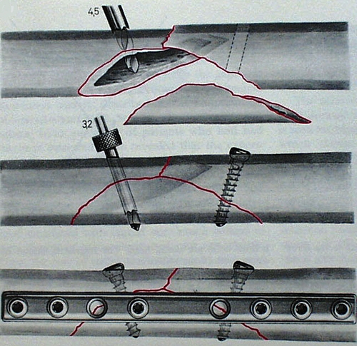
Figure 6. Neutralization plate used commonly in fractures with butterfly or wedge-type fragments after interfragmentary screw fixation of the wedge portion of the fracture.
One third tubular plate
- Plates have the form of one third of the circumference of a cylinder.
- Low rigidity (1mm thick).
- Oval holes – axial compression can be achieved.
- Uses – lateral malleolus, distal ulna, metatarsals.
- Limited stability.
- The thin design allows for easy shaping and is mainly used on the lateral malleolus and distal ulna.
- The oval holes allow for limited fracture compression with eccentric screw placement
Compression plates
- The fracture fragments are driven together, compressing them. This improves stability, allows primary bone healing with minimal calleous formation and improves the plates’ resistance to bending fatigue failure.
- Low profile with combination holes.
- Can eccentrically drill in order to compress.
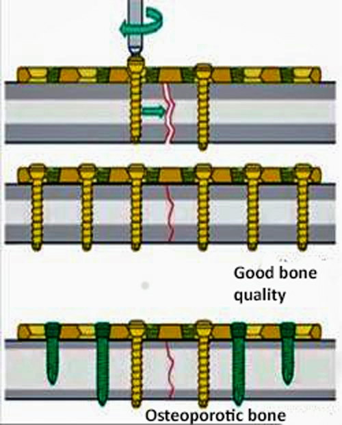
Figure 7. Compression plate
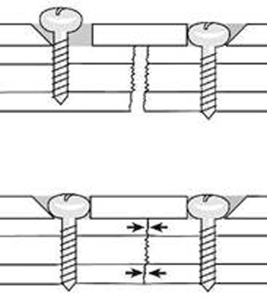
Figure 8. When the head of the screw advances downwards towards the bone surface,the screw and the fragment of bone it is attached to slide towards the centre of the plate. The fracture surfaces are driven together which creates a significant compressive force across the ends of the fracture.
- Compression can be:
- Static: does not change with time
- Dynamic: periodic partial loading and unloading

Figure 9.Axial compression result from the interplay between screw hole geometry and eccentric placement of the screw in the screw hole.The screw hole is like a portion of an inclined and angled cylinder
- Compression plates cancel out torsional, bending, and shear forces and create compression across the fracture site through specially designed self-compression holes in the DCP design. Torsional loads are resisted by the frictional force and interlock between the ends of the fracture components.
- Fracture fixation provides absolute stability and healing is by direct fracture healing with no callous formation. The fracture gap is reduced.
Limited-contact dynamic compression plate (LC-DCP)
- Represents a design change to overcome problems with DCP
- Structure:
- Structured undersurface
- Undercut screw holes
- Trapezoid cross-section
Advantages
- Improve blood circulation by minimising plate–bone contact.
- More evenly distribution of stiffness through the plate.
- Allows small bone bridge beneath the plate.
- The trapezoid cross-section of the plate results in a smaller contact area between plate and bone.
- The plate holes are uniformly spaced, which permits easy positioning of the plate.
- Undercuts plate holes; undercut at each end of the plate hole allows 4° tilting of screws both ways along the long axis of the plate. Lag screw fixation of short oblique fractures is thereby possible.
Bridging plates
- These plates are used to span a comminuted unstable fracture or bone defect in which an anatomical reduction and rigid stability of the fracture cannot be restored by fracture reduction.
- This concept combines the relative stability provided by the plate with the preservation of natural fracture biology to achieve rapid callus formation and fracture consolidation.
- The fracture fixation in this situation provides relative stability. Fractures treated with this more flexible fixation heal through secondary or indirect fracture healing with callus formation.
Buttress plates (antiglide plates)
- These are load-bearing devices that act to counter shear forces at a fracture site by converting them to compressive axial forces.
- These plates are placed at the apex of the fracture; the plate–screw construct acts as a load-bearing device.
- Force applied to the bone is perpendicular to the surface of the plate.
- Plate has a large surface area.
- The plate strengthens (buttress) a weakened area of cortex.
- The plate prevents the bone from collapsing during the healing process.
- The fixation to the bone should begin in the middle of the plate, i.e. closest to the fracture site on the shaft. The screws should then be applied in an orderly fashion, one after the other, towards both ends of the plate.
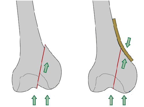
Figure 10. Buttress plate In fractures with a vertical fracture line, a buttress plate is necessary to counteract the vertical shear forces. The buttress plate prevents proximal displacement of the fragment.The buttress plate is added to enhance the stability and to counter axial load on the fracture, especially in osteoporotic bone.
Locking plates
- Conventional plating relies on the axial force from the applied screw torque and the friction between the plate and bone to resist loading.
- Locked plates do not require compression between the plate and bone due to the locking nature of threads.
- By firmly fixing the screw to the plate, the plate screw construct acts as a fixed-angle device; with the screws functioning as threaded locked bolts.
- Similar to the bars of an external fixator, plates are not applied directly to the bone, thereby providing elastic fixation, which facilitates fracture union through secondary bone healing with callus formation.
- Free of the need to apply the plates directly to the bony surface, the locked plate creates a more biological approach to the management of fractures, allowing for indirect reduction using minimally invasive percutaneous plating techniques.
- Indications for use:
- Osteoporotic bone
- Revising a fixation
- Small distal end segment (i.e. the fracture is close to a joint)
- Complex periarticular fractures
- Comminuted metaphyseal or diaphyseal fractures
- Periprosthetic fractures
- Principles of using locking plates:
- First reduced the fracture as anatomical as possible.
- Cortical screw should be used first in a fracture fragment.
- If the locking screws have been put, use of a cortical screw in the same fragment without loosening and retightening of the locking screw is not recommended.
- If a locking screw is used first avoid spinning of plate.
- Unicortical screws causes no loss of stability.
- With osteoporotic bones bicortical screws should be used.
- In the comminuted fractures screw holes close to the fracture should be used to reduce stain.
- In the fracture with small or no gap the immediate screw holes should be left unfilled to reduce the strain.
Tension band plate
- Plate on tension side.
- Eccentrically loaded.
- Compresses the fracture.
- A tension band plate converts tensile forces to compression forces on the convex side of an eccentrically loaded bone.
.jpg)
.jpg)
Figure 11(a) and (b) Tension band plate
Reconstruction plates
- Can be bent and twisted in two dimensions.
- Decrease stiffness than DCP.
- Should not be bent more than 15°.
- Used where the exact and complex contouring is required, e.g. pelvis, distal humerus, clavicle.
- Reconstruction plates are thicker than third tubular plates but not quite as thick as dynamic compression plates.
- Designed with deep notches between the holes, they can be contoured in three planes to fit complex surfaces, as around the pelvis and acetabulum.
- Reconstruction plates are provided in straight and slightly thicker and stiffer precurved lengths.
- As with tubular plates, they have oval screw holes, allowing potential for limited compression.
IM nails
- IM nails stabilise a fracture by acting as an internal splint, forming a composite structure in which both implant and bone contribute to fracture stability.
- The load sharing property of IM nails is fundamental to their design feature.
Advantages
- Compared to plating indirect technique of closed reduction and closed fixation.
- It is a zero moment device as it is positioned along the neutral axis of the bone.
- Compared to plating wide healing.
Disadvantages
- Suited only to certain fracture locations.
- Difficulties with fractures near the end of long bones.
Definitions
- Solid or hollow – hollow over a guide wire.
- Hollow can be open (slotted) or closed.
- Proximal and distal interlocking screws.
- Improve stability by resisting torsional and axial forces.
- Static or dynamic.
- Dynamic allows axial compression with early WB.
- Cephalomedullary nail – screw or blade into the femoral head. This improves stability such as with unstable proximal femoral fractures (sub-trochanteric).
Generations of nails
- First generation:
- Primarily acts as splints, minimal rotational stability, primarily relies on close fit to bone.
- Second generation:
- Improved rotational stability due to the use of locking screws.
- Third generation:
- Nails with various designs to fit anatomically as much as possible, to aid the insertion and stability.
Nail biomechanics
- Stability determined by:
- Nail design
- Number and orientation of locking screws
- Distance of locking screw from fracture site
- Reaming or non-reaming
- Quality of bone
Nail design
- Factors contributing to biomechanical profile include:
- Material properties
- Cross-sectional shape
- Diameter
- Curves
- Length and working length
- Ends of the nail
Material properties
Modulus of elasticity
- Titanium alloy is nearest cortical bone.
- Stainless steel is twice that of titanium.
Cross-sectional shape
- Determines bending and torsional strengths
Nail diameter
- Nail diameter affects:
- Bending rigidity D 3
- Torsional rigidity D4
Nail curves
- Governs how easily a nail can be inserted as well as bone/nail mismatch, in turn influences stability of fixation of nail in bone.
Nail length and working length
- A. Total nail length – anatomical length.
- B. Working length – length between proximal and distal points of firm fixation to bone.
- Length of a nail spanning fracture site from its distal point of fixation in proximal fragment to proximal point of fixation in distal fragment.
- Unsupported portion of nail between two major fragments.
Area moment of inertia
- Area moment of a solid nail = π ´ r4/4.
- If diameter = 10 mm, r = 5 mm, area moment = 490.
- If nail is hollow with 10 mm diameter and 2 mm thickness.
- Area moment = π (r1 – r2)/4 = 427.
- Therefore a solid nail of 10 mm diameter is slightly stronger in bending than a hollow nail having 10 mm diameter and 2 mm wall thickness, but the solid nail is much heavier than the hollow nail.
- If a 2 mm thickness hollow nail is made using the same material used to make the solid nail, diameter will be 16 mm.
- Area moment will now be 2198.
- Rigidity is therefore 4.5 times greater than that of a solid nail.

Figure 12. Moments of inertia relating to hollow IM nails
Polar moment of inertia
- Polar moment of inertia (solid nail) J = π ´ r4/2.
- Same example with solid nail diameter = 10 mm, r = 5 mm.
- Polar moment of inertia (solid nail) J = π ´ r4/2 = 981.25.
- Polar moment of inertia of a hollow nail constructed with diameter 16 mm.
- J = π ´ 84 = 6430 (6.6 times greater).
- As such a hollow nail is much stronger than a solid nail, i.e. the further the material is spread away from the neutral axis, the greater is its resistance to bending and torsional forces.
Biomechanics of external fixators
Advantages
- Versatile and used for:
- Bone transport
- Limb lengthening
- Angular correction
- Soft tissue reconstruction
- Contractures
- Serve many mechanical functions.
- Especially suited for open fractures and fractures with significant soft tissue injury.
- Apply quickly.
- Technically easy to perform.
- Can adjust at later date if needed.
- Soft tissues minimally disturbed.
- Allows access to wounds.
- Joints can be mobilised.
- Can dynamise
- Easy to remove
Disadvantages
- Pin site infection
- Mal-union
- Patient compliance needed.
- Psychological
Types of external fixator
- Simple pin fixator
- Unipolar
- Bipolar
- Clamp pin fixator
- Ring fixator
Pin size
- Stiffness proportional to (radius),4 so small changes in pin diameter greatly increases stiffness. This is the most significant factor affecting stability of the fixator.
- Larger pins provide more rigid fixator, providing less bending stress at the bone–pin interface and lower rate of loosening.
- However, the hole size acts as a stress riser; if the pin diameter is greater than 30% of the size of the bone the risk of fracture greatly increases.
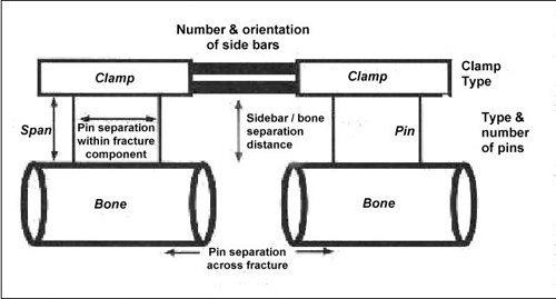
Figure 13. Factors affecting construct stiffness
Number of pins
- Two pins per fragment to prevent rotation, usually in same plane.
- A third pin in the fragment adds slightly to the resistance to bending and axial deviations, but little to rigidity.
Pin location
- Avoid zone of injury or future ORIF.
- Pins close to fracture as possible.
- Pins spread far apart in each fragment.
- Deformation perpendicular to the plane of two pins is best controlled with a third pin in that perpendicular plane. A third pin (C) out of plane of two other pins (A and B) stabilises that segment.
Bone frame distance
- The closer the frame is to the bone the more stable is the construct.
- Allow room for oedema and wound care (2–3 cm).
- External fixator stability increased by:
- Increasing the pin diameter.
- Increasing the number of pins.
- Increasing the spread of the pins.
- Multiplanar fixation.
- Reducing the bone-frame distance.
- Predrilling and cooling (reduces thermal necrosis).
- Radially preload pins.
- 90° tensioned wires.
- Stacked frames.
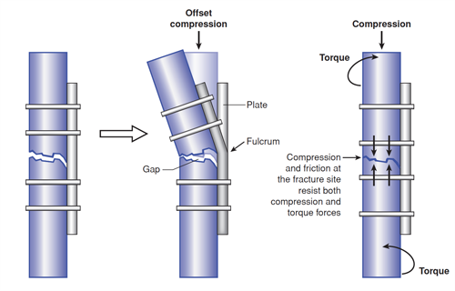
Figure 14 Left. When a gap is left on the cortex opposite that to which the plate is attached, bending of the plate at the fracture site can cause the plate to fail rapidly in bending..Right. Compressing the fracture surfaces not only allows the bone cortices to resist bending loads, but the frictional contact and interdigitation helps to resist torsion