TOPIC DETAILS

  Team Member Role(s) Profile
Paul Banaszkiewicz Paul Banaszkiewicz Section Editor
James Donaldson James Donaldson Segment Author

Wear

  • Progressive loss of bearing substance from the material as a result of chemical or mechanical action.
  • Wear is a function of use. So there will invariably be wear present in a total hip prosthesis in which average walking equates to the bearing surfaces being subjected to a million cycles of loading in a year.
  • Mode 1: wear debris generated with motion between two primary bearing surfaces
  • Mode 2: primary bearing surface rubbing against a secondary surface, eg. femoral head and shell after poly wear of the liner
  • Mode 3: two primary bearing surfaces with interposed third body particles
  • Mode 4: non-bearing surfaces rubbing together, e.g. backside wear, impingement
  • Fundamental mechanisms are:
    1. Abrasion
    2. Adhesion
    3. Fatigue

Abrasive wear:

  • Occurs when a soft material (e.g. poly) comes into contact with a much harder material (e.g. metal)
  • Microscopic asperities of hard material plough into the softer surface producing grooves
  • Some of the softer material may detatch causing wear debris
  • Third body abrasive wear is similar – the femoral head may be abraded by the extraneous particles, which may then abrade the poly at an accelerated rate.

BS3FAILUREARTHOPLASTY 1 .jpg

Figure 1. Abrasive wear

Adhesive wear:

  • Occurs when a junction is formed between the two opposing surfaces as they come into contact
  • The junction is held by intermolecular bonds
  • If it is stronger than the cohesive strength of the bearing material surface, fragments may be torn off and adhere to the stronger material

BS3FAILUREARTHOPLASTY 2.jpg

Figure 2. Adhesive wear

Fatigue wear (delamination):

  • Is a form of failure that occurs in structures subjected to dynamic and fluctuating stresses
  • Failure occurs at a stress much lower than yield strength
  • Mainly in total knee arthroplasties (TKAs)
  • Exacerbated by oxidation, subsurface faults, malalignment and thin ultra-high molecular-weight polyethylene (UHMWPE)


Figure 3. Fatigue wearBS3FAILUREARTHOPLASTY 3.jpg

  • With the highly conforming surfaces in total hip arthroplasty (THA), abrasive and adhesive mechanisms appear to be far more important than the fatigue wear mechanism.

Linear wear:

  • Loss of height of the bearing surface. Expressed in mm3/year 

Volumetric wear:

  • Volume of material detached from the softer material as a result of wear. Expressed in mm3/year
  • Volume of wear is directly proportional to the load applied and sliding distance
  • Volume of wear = load ´sliding distance
  • The wear coefficient describes the volume of wear per unit load and sliding distance.

Volume of wear mm3 = k [mm3/N mm] ´load [N] ´sliding distance [mm]

K [mm3/N mm] = volume of wear [mm3]

Load [N] ´sliding distance [mm]

  • Wear coefficient is related to the material combination and wear environment (lubrication).
  • For THA, the sliding distance is the diameter of the femoral head. So, a small diameter head could reduce wear. But this would also mean a smaller contact area and increased depth of wear.

Factors that determine wear

  • Patient:
  • Weight (applied load)
  • Age at surgery and activity level
  • Implant:
  • Coefficient of friction between pairs of materials
  • Roughness (of the counter surface)
  • Toughness
  • Hardness of the materials
  • Sliding distance for each cycle depending on the diameter of the head
  • Number of cycles over time
  • Surface damage
  • Third body wear
  • Load factor: individual motion pattern
  • Polyethylene factors
  • Joint factors:
  • Type of lubrication
  • Hardness:
  • Hardness of a material is defined as the resistance to indentation
  • Hardness is not a basic mechanical property, but instead is derived from a combination of other mechanical properties, e.g. strength and stiffness
  • Hardness determines the wear resistance of a material
  • The harder a material, the greater the wear resistance than a softer material under the same loading conditions
  • Roughness:
  • Metal factor: an increased roughness of the countersurface can result in accelerated wear of the polyethylene bearing surface
  • Toughness:
  • Toughness is a material’s ability to absorb energy up to a fracture
  • Toughness is derived from both strength and ductility of a material
  • A tough material is normally both strong and ductile
  • Load factor: individual motion pattern:
  • Polyethylene wear is a factor of motion pattern. In laboratory tests, linear motion loading pattern resulted in less wear compared to crossing motion loading
  • Polyethylene factors:
  • Sterilisation: polyethylene wear is increased in gamma irradiation in air
  • Manufacturing: highly cross-linked polyethylene has higher wear resistance property and its use has been shown to reduce wear
  • Polyethylene thickness
  • Position of the acetabular cup:
  • An increased inclination angle of the cup in the frontal plane (i.e. abduction angle) is significantly associated with a greater wear rate.
  • Lateral displacement is a risk factor for increased wear while medial displacement is a protective factor. This is in accordance with the biomechanical concept that the centre of rotation should be as medial as possible to reduce the resultant torque and risk of hardware loosening when the femoral offset is unchanged.
  • Third body wear:
  • Wear in THA is also related to the presence of third body materials
  • Lubrication:
  • Wear is also dependent on adequate lubrication
  • Without this wear particles would not be efficiently removed and result in accelerated third body wear.

Consequences of wear

  • Synovitis
  • Osteolysis and loosening
  • Increased friction of the joint
  • Malalignment and catastrophic failure
  • Immune reaction
  • Systemic distribution of wear particles
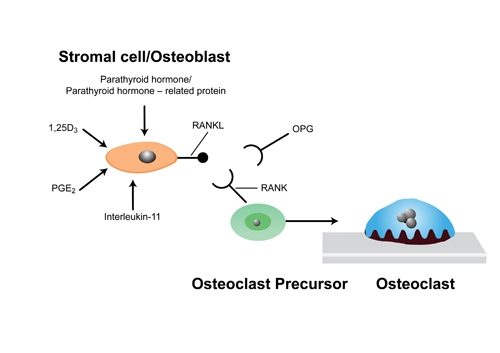
  • Wear particles are phagocytosed by macrophages releasing soluble pro-inflammatory mediators (cytokines, prostaglandins).
  • Particles 0.1–10 μm are biologically active.
  • Mediators released near to bone cause osteolysis by stimulating osteoclasts to release oxide radicals and hydrogen peroxide, which resorbs bone.
  • Results in aseptic loosening and failure.
  • Osteolysis is self-sustaining. As it loosens abrasion and fretting occur which increases the debris and wear particles.
BS3FAILUREARTHOPLASTY 4.jpg

Figure 4. Cellular basis of Osteolysis 

Risk factors for osteolysis

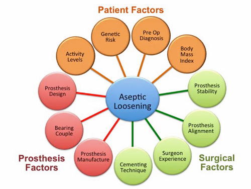
  • These can be broadly divided into patient, surgical and prosthesis-related factors.
BS3FAILUREARTHOPLASTY 5Harry .png

Figure 5. Summary of risk factors that influence the development of aseptic loosening

Classification of loosening

  • The progressive development of radiolucent lines suggest loosening.
  • This needs to be differentiated from age-related expansion of the femoral canal and cortical thinning (no sclerotic line).
  • Loosening is also more irregular, with variable areas of cortical thinning and ectasia.

Classic reference1

  1. DeLee JG, Charnley J. Radiological demarcation of cemented sockets in total hip replacement. lin Orthop. 1976; 121: 20–32.
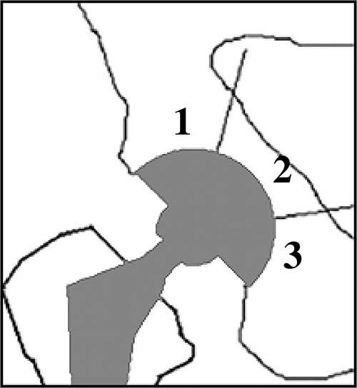
  • DeLee and Charnley described a simple radiographic zonal classification system for the assessment of acetabular osteolysis.
  • Acetabular cup loosening was assessed around the circumference of the socket and categorised into three zones (types I, II, or III) in the anteroposterior (AP) film.
  • Loosening was diagnosed when a change in the position of the component had occurred or when a continuous radiolucent line wider than 2 mm was noted.
  • Loosening of a cemented acetabular component is usually assessed using the criteria of Hodgkinson et al.2The DeLee and Charnley classification provides for a descriptive analysis of the zone in which the osteolysis is present.
BS3FAILUREARTHOPLASTY 6.png

 Figure 6. DeLee and Charnley Zones

Classic reference3

  1. Gruen TA, McNeice GM, Amstutz HC. “Modes of failure” of cemented stem-type femoral components: a radiographic analysis of loosening. Clin Orthop 1979; 141: 17–27.
  • Previous attempts made to standardise the assessment of radiographs so that rates of radiological loosening at different centers could be compared had been incidental and not performed witha large series of patients.
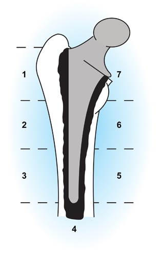
  • Gruen et al. developed a widely used system in which the femoral component interface is considered in seven zones. These allow the location of cement fractures and of lucent lines either at the cement–bone or the cement–prosthesis interface. It is the progressive changes that are seen in serial radiographs that are important in diagnosing femoral stem loosening.
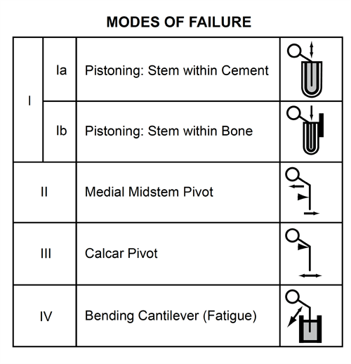
  • Gruen and colleagues also comprehensively review the four Gruen mechanical modes of cemented femoral stem failure.
BS3FAILUREARTHOPLASTY 7.jpg

Figure 7. Gruen radiographic classification of femoral stem loosening

  • The four modes of femoral stem failure are:
  • Mode Ia is stem pistoning within the cement, which occurs secondary to an incomplete cement mantle or loss of proximal medial cement support.
  • Mode Ib consists of stem/cement subsidence within bone. This mode of failure is most familiar to orthopedic surgeons evaluating radiographs of loose total hip replacements.
  • Mode II is medial midstem pivot, which is characterised by medial migration of the proximal stem coupled with lateral migration of the distal stem tip. It is caused by weak proximal/medial (calcar) support and lack of distal cement support.
  • Mode III failure consists of medial lateral toggle of the distal stem due to lack of distal stem support. This is the windshield type of loosening.
  • Mode IV failure is cantilever fatigue failure characterised by partial or complete loss of proximal support with subsequent medial migration of the proximal stem while the distal end remains rigidly fixed in cement. This mode of failure can be recognised early by radiolucencies developing along the proximal lateral cortex (convex) surface of the stem.
BS3FAILUREARTHOPLASTY 8Harry .png

Figure 8. Modes of cemented femoral stem failure according to Gruen

Classic reference4

  1. Harris WH, McCarthy JC, O’Neill DA. Femoral component loosening using contemporary techniques of femoral cement fixation. J Bone Joint SurgAm 1982; 64(7): 1063-1067.
  • Harris et al. proposed a radiological classification system for femoral stem loosening. Three categories were defined: definite loosening, probable loosening and possible loosening.
  • Definite loosening:
  • Subsidence of the component.
  • Fracture of the stem.
  • Cement mantle fracture.
  • Radiolucent line between the stem and cement mantle not present on the immediate postoperative radiograph.
  • Probable loosening:
  • Radiolucent line at the bone/cement interface that is either continuous or over 2 mm wide at some point.
  • Possible loosening:
  • Radiolucent line at the cement/bone interface between 50 and 100% of the total bone/cement interface not present on the immediate postoperative radiograph.
  • Harris later abandoned the radiographic criteria for probable and possible loosening. Studies of well-functioning, long-term mechanically stable femoral components retrieved at post mortem had shown that most cement–bone radiolucencies represent endosteal remodelling rather than disruption of implant fixation. Harris felt that the radiographic findings leading to the diagnosis of probable or possible loosening were no longer valid or useful.

Other modes of implant failure

  • Instability
  • Infection
  • Periprosthetic fracture

Periprosthetic fractures

  • Increasing in incidence.
  • Can be intra or postoperative.

Femoral intra-operative fractures

  • 3.5% in uncemented.
  • 0.4% in cemented.
  • Proximal:
  • From bone preparation and prosthetic insertion or dimension mismatch
  • Middle:
  • From excessive force during exposure or bone preparation
  • Distal:
  • Straight stem tip impacted against femoral bow
  • Risk factors:
  • Impaction bone grafting
  • Female
  • Technical errors 
  • Uncemented implants
  • Osteoporosis
  • Minimally invasive surgery

Acetabular intra-operative fractures

  • Cemented 0.2%.
  • Uncemented 0.4%.

Risk factors:

  • Under-reaming
  • Elliptical cups 
  • Osteoporosis
  • Uncemented cups
  • Dysplasia
  • THR for trauma

Treatment:

  • If stable – can observe or partial weight-bearing (PWB)
  • If unstable consider adding screws, large cup or ORIF of the fracture

Femoral postoperative fractures

  • Early:
  • Uncemented prostheses tend to fracture within 6 months. Likely from stress risers during reaming and broaching.
  • Wedge fit tapers cause proximal fractures.
  • Fully coated cylindrical stems may cause a split in the femoral shaft.
  • In revisions fractures tend to occur at the site of a cortical defect or if the defect has not been bypassed more than two cortical diameters.
  • Late:
  • Cemented stems fracture around the tip or distal to it.
  • Risk factors:
  • Inadequate calcar cancellous bone removal and subsequent calcar resorption
  • Varus stem
  • Osteolysis
  • Uncemented prostheses
  • Revision procedure

Vancouver classification5

  • A. Trochanteric fracture. Often related to osteolysis.
  • AG. Greater trochanter
  • AL.Lesser trochanter
  • B. Around the stem.
  • A B1. Well fixed prosthesis
  • B2. Loose prosthesis, good bone
  • B3. Loose prosthesis, poor bone
  • C. Distal to the stem

BS3FAILUREARTHOPLASTY 9.png

Figure 9. Vancouver periprosthetic hip fracture classification.

TKR peri-prosthetic fractures

  • Intra-operatively:
  • Femur – anterior cortex during rod insertion at metaphysis/diaphysis junction
  • Tibia – longitudinal fracture of diaphysis during stem insertion or transverse fracture of metaphysis with finned or pegged implants
  • Postoperatively:
  • Lewis and Rorabeck classification:6
  • Widely used system dividing the injury into three types:

1. Undisplaced and prosthesis stable.

2. Displaced and prosthesis stable.

3. Displaced or undisplaced with loose prosthesis.

  • Lewis and Rorabeck advocated non-operative treatment for type I fractures, either closed reduction and fixation with an intramedullary nail or open reduction and internal fixation with a plate for type II fractures, and revision of the prosthesis using long stemmed revision implants or structural allograft depending on the bone stock available for type III fractures.

BS3FAILUREARTHOPLASTY 10Harry.png

Figure 10. Periprosthetic knee fracture classification.

Previous
Next

References

  • 1. Banaszkiewicz PA. Radiological Demarcation of Cemented Sockets in Total Hip Replacement, in Classic Papers in Orthopaedics. Springer, 2014, pp. 39–41.
  • 2. Hodgkinson J, Shelley P, Wroblewski B. The correlation between the roentgenographic appearance and operative findings at the bone-cement junction of the socket in Charnley low friction arthroplasties. Clin Orthopaed Relat Res 1988; 228: 105–109.
  • 3. Banaszkiewicz PA. “Modes of Failure” of Cemented Stem-Type Femoral Components: A Radiographic Analysis of Loosening, in Classic Papers in Orthopaedics. Springer, 2014, pp. 35–38.
  • 4. Banaszkiewicz PA. Femoral Component Loosening Using Contemporary Techniques of Femoral Cement Fixation, in Classic Papers in Orthopaedics. Springer, 2014, pp. 43–46.
  • 5. Duncan C, Masri B. Fractures of the femur after hip replacement. Instructional Course Lectures 1994; 44: 293-304.
  • 6. Lewis P, Rorabec C. Periprosthetic Fractures. In: Engh GA, Rorabeck CH, eds. Revision Total Knee Arthroplasty. Baltimore: Lippincott Williams & Wilkins, 1997.